|
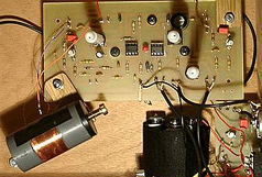
When I originally wound my own oscillator coils with 30 gauge
enameled wire as seen in
this Ultimate 2b
theremin constructed by Dominik, I could not get much more than
three linear octaves.
Visit Dominik's
webpage and listen to his sound samples in the upper left corner of his page. He
is a master theremin builder today and uses built in mechanical spring
reverbs for a nice affect.
Observation:
I upgraded my Ultimate 2b pitch oscillators from 30 gauge wire on an air core coil to 22 gauge wire on a
ferrite core in my
later RS Illusion
theremin design. Using two heavy gauge 100 uh choke/coils per
oscillator to give me a center point and
to my surprise, it expanded the pitch field from three
linear octaves out to just over
five linear octaves. This was using the
Lev Antenna on both, with no other circuit change.
A five octave linear spread over a 18" to 20" pitch field
distance is an ideal number for arm reach and playing distance.
 |
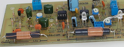 |
| Going
from an air core coil on the left to a split
ferrite coil for a center tap on the right, the
number of linear octaves increased from three to
just over five. The oscillator circuit
configuration and values remained the same. |
Note: in a linear
pitch field there are no almost linear octaves,
five linear octaves is five from Null to the Antenna.
I
tried a no oscillator tank capacitor approach but PN
junctions introduce their own capacitance which caused a distorted wave shape, it is important for me to
use the pure heterodyne generated signal for sound and
character.
My guess is the heaver 22 gauge enamel coated wire on a ferrite core improved the circuit Q factor considerably which in turn
delivered more current into the antenna tuned as part of
the tank circuit. In other words reduced
coil wire resistance.
Ferrite
core coils track or counter balance one another very
nicely, it is the transistors used that cause issues.
My
tube/valve theremin runs a hotter signal at the antenna and
interestingly the linearity effect is even better with more octaves.
The oscillator split coils I use in my RS Illusion
theremin were not shielded and so I must place the pitch
and fixed oscillators farther apart. This is why my two oscillators are on separate boards. The two oscillators interacting within close proximity to one another can cause unwanted wave shapes or distortion in the
detected audio wave, sometimes good but most of the time very bad.
|
THE KEY: One improvement seldom used
in very early electronics that lead directly to the
improvement of modern RF electronics is the use of ferrite
cores for higher Q circuits. The ~ 900 kHz theremin operating frequency keeps
the design practical. |
The amount of energy available to the pitch antenna
determines the number of linear octaves. In a Lev
Antenna pitch field there are no non-linear octaves just
more or less octaves. Normally this is 3 to 7 octaves.
Here is one of several interesting letters I received from a dear friend of Lev's.
It hints
at how he had trouble finding parts in his later years of experimenting in Moscow.
Lev Sergeyevich is not often thought of as experimenting with transistor circuits and ferrite coils but
without doubt he did. He experimented until his death in 1993.
The true marvel . . .
"Octave & key spacing is an early "man made control" of
the piano and the theremin embraces it." The Termen
Effect is a good phrase to capture this very unique relationship.
|
Below are some important behaviors
worth mentioning.
Note 1: Fine tuning for the Null point on a transistorized heterodyne theremin can be accomplished by
slightly varying the circuit current using a variable resistor on the emitter or base of the oscillators
of a bi-polar transistor. This is manipulating the junction capacitance of the transistor
similar to a varactor diode which controls the oscillator frequency.
Note 2: Variable caps should be avoided in a theremins pitch or fixed oscillator to avoid extra temperature drift
issues caused from room temperature fluctuations.
Note 3: In a transistorized theremin it is important to use two oscillator transistors that come from the same manufactures batch # so they have very similar characteristics. Most thermal drift
develops from the mismatch here. To minimize thermal drift you want the two oscillator transistors
to behave like identical twins.
Note 4:
There "are not" extra non linear octaves in the
perfectly linear pitch field,
the linear octaves exist between the Null point and the pitch antenna. The pitch field spreads out wider
adjusting the pitch tuning knob as usual but it still remains
linear. In the phrase "three linear
octaves", linear means they line up in a relationship
to a musical scale or parallel to piano key spacing.
The notes or intervals are all the same width right up next to the
antenna.
Linearity
gives you precision note control of the theremin. I adjust my
Theremin to play one octave lower with my hand closed which gives me a
predictable one octave higher jump snapping my fingers open. One
octave of notes is held in the fingers of my hand. Here is an old sound sample
from my tube theremin Linearity
Test.mp3
(200k)
Master
those seven and play with the same accuracy anywhere in the
theremin playing field. Similar to the Carolina Eyck
method. Your
pitch adjuster allows you to narrow or widen the octave width to match the size
of your hand for accurate aerial fingering.
|