<=Main Page    A True Theremin

 Opto-VCO

RS Optermen II  &  Electro-Theremin  &  Theremin Cello
This is the Engine

11.20.18

Still waiting for that first builder to start a discussion!

The first recorded sound after breadboard construction of the Optical approach called the Optermen II .mp3 (550 kb) using the clean beam of a LED flashlight. The potential of this circuit board design adapts readily into an Electro-Theremin or Ondes Martenot?

This new Opto-VCO design has Pitch and Volume control

It develops a harmonically balanced analog sound, better than many theremins!


Note: PT1 & PT2 & PT3 are photo-transistors which respond better than a single LDR light dependant resistor.

Verify PCB connections to schematic above, let me know of any errors? Mouser list needs update.

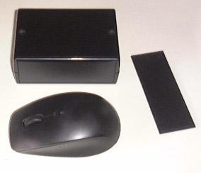
This layout matches the enclosure on the Mouser List - TRS jack can mount in either direction

PT3 & LED1 mount in 5 mm terminals facing away from the board. Then insert PT3 & LED1 and fold them over the top of the terminal so they point at one another. Add the light blocking black tube which is now about 1/2" above the board. Bending the black tube at the center is what controls the volume response.  


- You get to think up the best method for Light Control Interaction or Electro-Theremin mechanics -

I added pads in front of PT1 & PT2 for a Potentiometer, this is for a Electro-Theremin/ Tannerin mechanical add-on.

You might need a black plastic sleeve around the phototransistors to block the light coming from the sides. This will make the light exposure more directional toward the phototransistors front lenses. The photo-transistors are set back when using the black enclosure.

The Audio Output is taken from a 1/8" (3.5 mm) stereo jack into your amp or computer.

The AAA six volt battery pack will last for years, even if left on! The current drain is under 4 ma.


This homemade pcb method using a PDF is a skill you should develop. If there is a lot of interest in this project I will get some commercially made PCB's in the future and furnish the black rubber tube.

  Mouser Parts List
Updated 11.20.18

Top Opto-Silkscreen.pdf            Bottom Opto-Copper.pdf
If image not visible scroll down on PDF page

Youtube video on PCB making


Expand Your Imagination

If you explore this project you might be on the cutting edge of something original.

- This Opto-VCO pc board is the engine to get you started -

In the sound sample I am sweeping a LED flashlight beam, There is timbre control by focusing more light on one photo-transistor than the other.

<= Actual Enclosure & back panel, mouse gives size perspective.


Buy this $20 frequency meter to find your musical notes precisely. I have one and it also works good with a 1 Mhz theremin. 

From Amazon  


Post your results in my Chat Forum. Start a thread and title it "I Want To Make the Opto-VCO board". Come join me for some basic talk!  If you have an idea that would improve this design, share with everyone your creativity.

If you develop your own version of this design and post to YouTube, I will be happy to post a link  here.

Good Luck from oldtemecula

.


Electro-Theremin / Tannerin
This will need its own webpage eventually

This Opto- VCO board design has a nice sweep and is drift proof... really!

Sound sample.mp3 using a potentiometer, now to figure out the best mechanical movement, right and left is un-natural.

If you want to etch the pcb for this project contact me in my Chat Forum and I will email the iron-on PDF.

One click Mouser Parts List  -  This list has two Potentiometers to get you results.

I will advance my build using the Lazy Susan or Pendulum approach which does not use the Pot. 

Radio Shack has the best 100K potentiometer that I have found so far with an Audio Taper and long 1/4" shaft. With the standard audio taper the musical notes rise sweeping counter-clockwise. 

In the photo wire connections are made to the right two lugs.

Also at ebay in UK


Current oldtemecula Opto-VCO Features:

No RF or Hand Capacitance is used giving rock solid stability.

No Power consumption or Sound while the box sits idle in normal room lighting.

Battery drain of less than 5 ma using a TLC555 during tone generation.

Frequency using the TLC555 design is drift proof over battery decay cycle.

You will have a perfectly linear pitch sweep over 4 octaves using an Audio 100K Pot.

Musical notes rise using a counter-clockwise turn of the Potentiometer. (There are audio Pots in reverse)

Add-on feature for Staccato or Vibrato enhancement.

Volume Control with swift On Attack, this can be mounted on the pitch sweep potentiometer.

Volume Control with a 10" shading window, visually similar to the hand motion of a RCA Loop,

The Volume increases as the Hand approaches the box.

An excellent solid-state sound that can be tweaked into something better.

I have a clever method of marking individual index cards with the proper note positions for specific melodies.

Use this freeware for accurately marking-off your musical note locations or use the meter from Amazon above.


I should have a solid Potentiometer mounted by the end of the week to play a simple tune. "Good Vibrations"