<=home


Electrodeum Pitch Antenna
The βecker Electrode

12.13.20

- Tanner P. if ever you get here, do not look at what others suggest is going on with the theremin pitch antenna and how it works. Explore it from scratch, stay pure in your understanding -

 The linearity and rich sound of this project revolves around this pitch electrode concept.

Maybe the miracle of the 100 year anniversary is an improved sound and that all theremin designs can now feel and play the same... then it is much easier to play different models. 

12.13.20 My Pitch RF frequency is 900 kHz, I am always amazed that in theremin design often it guides us to 450 kHz or 900khz. My spring coil Electrodeum works at 900 kHz yet hooking it up to a signal generator I doubt you would see anything special at 900 kHz. Here is a Theremin World webpage that an RF phenomenon is occurring around 900 kHz relative to earth grounding that no one bothered to explore further. Probably it is nothing unless you are the curious type.

~ 900 kHz Phenomenon                     PDF of TW Webpage


Ideal Field Linearity
is having a response that approaches a piano keyboard layout note for note.

Why this works is the spring is a resonating circuit. A coil spread surface compared to a normal pitch antenna distributes the surface capacitance in a way that the outer field ratio has more capacitance due to geometry than normal pitch rod and the inner field has less capacitance proportional to a standard pitch antenna rod.

When you have ideal Linearity, you set one octave width to match the size of your hand for aerial fingering and all the other octaves widths will also match right up next to the right side of the antenna! 

With the Electrodeum Pitch Antenna the tuning is parallel to the variable oscillator circuit which simplifies and improves the response. This Pitch Antenna tuning is much more forgiving than the EtherWave Standard series antenna tuning.

A theremin MUST have a good earth ground, often achieved by using your main power amp that has a three prong power plug into the wall receptacle. 

The blue wire on the Ant2 side is not connected to anything, I call it a tickle wire which picks up the RF field from the two oscillators which is mixed in D1 1N914. A theremin is basically two RF transmitters detected by a diode detector like a crystal radio works. The large 1k Pot is used until I get a panel Pot mounted.

LTspice by dewster

My adversary unconsciously drew this 8.15.19, the birthday of Lev Sergeyevich Termen.

.


Sand off half of the edge of the wood stick for easier insertion. In the right picture with the stick fully inserted mark like you see in red. Cut off the extra at the outside of the red line. Critical, this should not give the spring coil any more than 1/2" (13mm) stretch. Slip the stick in so it rests properly against the inside of both loops. Add epoxy at the contact point of the stick and loop, this keeps it from slipping out of place.    
The C-253 spring has a special quality. If you send me pictures of your completed Phoenix Build and are outside of the USA I will send you the spring coil at no cost to complete your project. I can also include the Vactrol. These two sent to Europe is a $50 value, my gift, a reward for your success.

My setup tunes to 900 kHz

Note: Use a 1/2" (13 mm) stretch on the spring to create a tuned coil antenna. The spring has an light insulating coating between turns. 

Century Extension Spring (substitute at your own risk)
C-253 9/16" x 16-1/2" x .054" (14.3 mm x 419.1 mm x 1.372 mm)
16 turns per inch (approx. 252 turns at a ½" I.D. diameter)

The plastic tube looks nice but it is an important shield against air currents and static discharge.

Spring Coil - Amazon

Plastic Tube - Amazon

Acorn Top - Amazon

1/4" Wood Stick any hardware store

The un-stretched C-253 spring end coil end to end should be 15 5/8" or 15.625" or 39.7cm

I insert a 1/4" wood square stick cut to size 16 1/8" or 16.125" or 41cm long. The ends press against the inside of the double loop mounting rings.

After the stretch it should be just over 16.125" or 41cm edge to edge between the end loops.

The base of the antenna is attached to a high current 3.3mh High Q choke to earth ground.

There seems to be a 3/8" (10 mm) variation in spring lengths from different vendors, always use the C-253. Add the 1/2" or 13mm stretch and hope it works.

Link - Plastic 3/4" or 5/8" id 21" sleeve to keep circulating air off the sensitive spring/coil pitch antenna and protect against static discharge. 

That dangling choke mounts on the PCB. 

PVC sprinkler pipe will also work but not as pretty as clear acrylic pipe.


.


12.08.20

Future Electrodeum Antenna Experiments

Does the driving oscillator emitter show a dip or rise in current at Pitch Antenna resonance?

Can a lack of or proper earth ground reveal itself in the emitter signal wave shape?

Is the Electrodeum Antenna more or less susceptible to noise picked up from RF maybe use a plasma gas globe as noise source or the spark discharge from a BBQ piezo starter or 50/60 Hz from the wiring in the walls?

Can ideal Pitch Antenna tuning be done using the heterodyned audio signal amplitude after the first audio amplifier section? Set a fixed tone like 440 Hz, adjust variable oscillator frequency slightly then adjust the fixed oscillator back to 440 Hz. Has the audio signal amplitude after the detector changed? Keep doing this to find the peak or dip for ideal Pitch Antenna tuning. 

You always want the variable oscillator tuned just above the resonant frequency of the antenna circuit. Otherwise detuning the antenna by the hand influence could cross over the variable frequency which will cause a flat or null response in the pitch field.

Short the Spring Coil end to end to stop it from resonating while doing some experiments.

If RF plays a roll in the Pitch Field placing a screen mesh grounded through a 3300 uh choke to ground, between your hand and the Pitch Antenna should take most hand capacitance effects out of play leaving mostly RF which is more difficult to block. 

Does RF finding an easier path to flow through your arm than air affect the capacitive reactance of the variable Pitch Oscillator shifting its frequency a bit, maybe even six musical octaves? This is a response to a change in the current flow in the actual antenna rod or spring coil.

There are thermal drift advantages by connecting the signal wire about 1/4 the distance up the inside of the spring/coil. This needs more experimentation.

12.09.20  The Pitch 
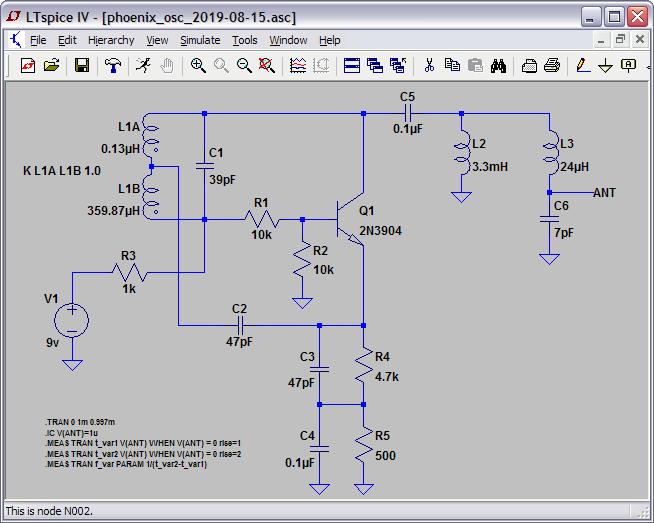
Oscillator frequency at 900 kHz is important in my research.


../oscillators/images/phoenix-osc.jpg

The RF tuning of my oscillator design can be done by varying the circuit reactance at various points.

R20 varied by 220 ohms to change the current flow in the oscillator tank LC is used for the main Pitch frequency or Zero Beat adjustment. This current change also has a slight affect on the PN junction capacitance, but this is more affected by room temperature changes. If R9 has a .1uf capacitor placed across it the tuning affect of R20 is cancelled out.

Pot-3 balances the reactance of both oscillators so they behave similar and this balance will cancel out thermal drift within a certain range. If Pot-3 has a .1uf capacitor placed across it the balancing effect between oscillators cancelled out.

L4 3300uh if a 50 ohm resistor is placed in series with this choke it can swing the reactance of the tank LC for oscillator tuning. If the 50 ohm pot has a .1uf capacitor placed across it the tuning effect on the oscillator is cancelled out.

Using vacuum tubes this 50 ohm potentiometer might be more practical for tuning as you can place the Pot anywhere.
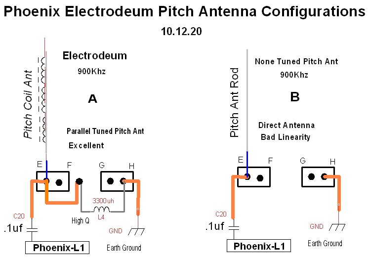
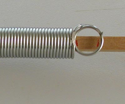
Pitch Antenna tuned or un-tuned has a RF current feeding it. Rather than current flow it is probably more like electron vibration which transposes into RF energy a phenomenon of Nature.

The question is why does the Pitch Antenna respond to the proximity of the hand. Is it straight forward hand capacitance or does Pitch Field conductance of the RF enhance the response when the Pitch Antenna is resonating. The wave length of the RF at 1 MHz is 300 meters or 984 feet, this is the first reason why a good earth ground is necessary, the energy must go somewhere or it will distort the proper function of the theremin variable oscillator.

A resonating Pitch Antenna better distributes the musical notes in the Pitch Field. It is not quite perfect but close enough so I call it Ideal Linearity.

The goal is to simplify the best method to achieve the Ideal Musical Note spread in the Pitch Field and then have this consistency designed into all theremin models. 

.


Some Pitch Electrodeum facts:

Without the L - 3.3 mh pitch spring antenna base choke, perfect linearity is still there but the variable oscillator must be tuned more precisely to the antenna resonant frequency of ~900 kHz.

Even without an earth ground linearity is there, the spring tuning seems to stand on its own which is a benefit, why it may work with all theremin designs.

The 13 mm stretch in the spring is critical and less stretch is better than more. Also this keeps the springs coils from shorting side by side.

Using the base L4- 3.3 mh high Q coil to ground (5 ohms) the variable oscillator tuning becomes very broad, 850 kHz to 950 kHz. 

There are thermal drift advantages by connecting the signal wire about 1/4 the distance up the inside of the spring/coil. This needs more experimentation.


This Video

The left side red line 2" (50mm) from the spring coil Pitch Antenna is G7, normal field compression begins here, that is 7 playable octaves. 

Demonstration by Valery Shamarin of St Petersburg, Russia

.