Ant-V
volume control is very sensitive and would never be connected directly to a
volume loop, use the loop more as a prop. The blue wire is
maybe 8" in length and sensitive out to 24" for a very
wide or narrow volume window.
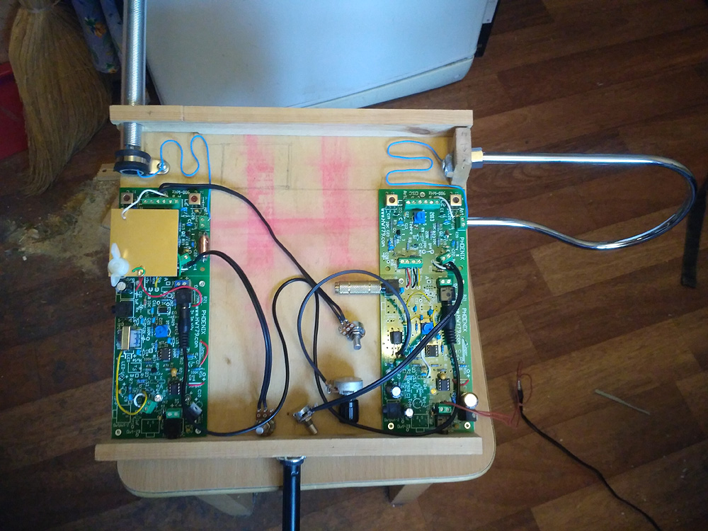
A. Experimental -
There are two areas that the main thermal drift originates, one is the
oscillator transistor junctions and the second is the temperature change in
the environment around the pitch antenna. I have observed placing the
connecting wire to the B antenna in a strategic spot can offset
some drift. This is about 1/4 the distance up from the base, needs
more testing. When you find the ideal spot fold the spring over to
spread out the loops and run the connecting wire down the center. The spring
coils should move freely on the 1/4" wood stick and inside
the plastic sleeve.
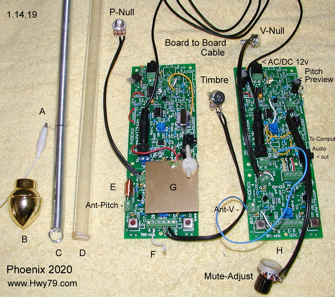
B. This gold cap
will hide how the spring coil is suspended at the top of the
tube.
C. If you look
closely you can see the 15" stick pressing the inside of the
mounting end coil.
D. A small piece of
the 1/4" stick is glued to the inside of the plastic sleeve
to suspend the spring coil.
E. This is the
L4 3.3
mh high Q choke connected directly to the base of the spring coil
and earth ground. It has about 5 ohms of dc resistance, amazing it
does not ground out the entire operation, instead magic happens,
perfect pitch field linearity of any width.
F. I call this a
1.5" tickle wire, connected at terminal T1 B, one on each board fine tunes for the proper
wave shape. The idea comes from my radio background and
experimentation.
G. The b-antenna
creates a stronger capacitive pitch field and this pitch side shield limits feedback to the
fixed oscillator. Also it
protects the L3 mixer/detector combo which is at a very high impedance from
picking up 50/60 Hz hum. This method of mixing combines the
inductive field from all the surrounding inductors. L1 L2 L4
H. This is the
volume side 1.5" tickle wire, fold back around by L1 as seen, this
will fine tune
for the proper wave shape.
Seen are the four
potentiometers, Pitch Null, Volume Null, Timbre, Mute adjust.
These would replace the pot holes if you are using the
EWS box.
The between board
connecting TRS cable can be 1.5' in length if you are using the
EWS box.
Having the
Volume Control separate from the Pitch section allows others to design
even more creative approaches.
|