- This website is
about recapturing the original
classic theremin sound -
Raw
Sample.wav
RCA buzzy bottom then intimate, no thin whistle
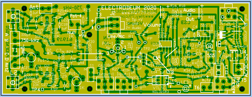
The pitch & volume boards are connected together
through the J2 TRS jack. 12 volt
power normally goes to the volume board first then passes a regulated 9 volts through J2 TRS
jack to the pitch board.
The RF section uses 9 volts, the pitch board audio section 5 volts. All this from a
single 12 volt AC transformer with ground.
Amazon
Latest
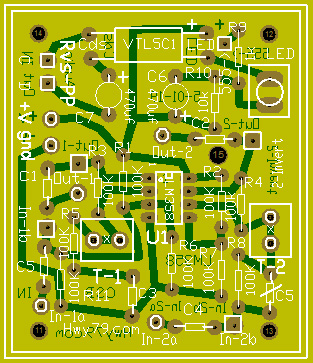
volume board PDF date is 6.19.19 PDF
toner transfer posted on home page
The reverse pitch
preview only heard when volume control quiet is found as an add-on
at the bottom of page.
Use
a cable
inline volume control from the pitch preview jack to the
ear bud.
If volume is low increase R12-220k to 330k then readjust Pot-1 to
line-level.
T6
Mute can be a switch or 10k panel mounted potentiometer -
experimental.
Pot-5
1/4 turn cw, Pot-2 fully cw,
Pot-3 fully cw
Mount these two first to avoid confusion
C7 = 100pf
/ Mount next C17,
C19 = 100pf
R3 & R10 on left
side of Q3 changed to 100k, also study R23-220k to 100k
The volume
response can be on/off... adjusted out to 18" of fade and you set the
distance of Off from the loop.
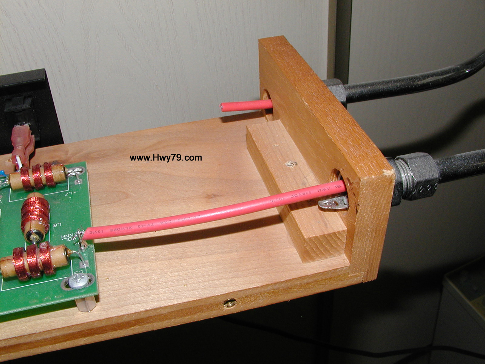
Caution:
Touching the
Phoenix volume loop
will turn the sound back
on
It
overwhelms or stalls out the sensitive variable volume oscillator. To prevent
this
do not use a direct connection to the metal loop... feed in
about 8" of insulated wire, then check the overall response, adjust if needed.
For solid loops see below.
- Using high voltage wire also "protects" against static discharge -
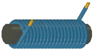
If your
Volume Loop is a solid rod then wrap insulated wire on one end for gradual
build up of capacitive
coupling. Keep wrapping until grabbing the loop stalls out the volume
oscillator and the sound comes back on, then remove a few wraps until
stable. I have not
tried the one below.. so experiment.
T-1 &
T-2 are "not used" unless you need adjustable gain instead of 1:1
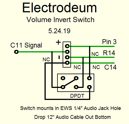
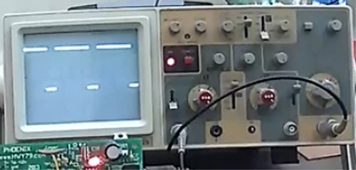
On volume
control board the output of the 555 at pin 3 should have a downward
narrow pulse to work properly. If not use the new add-on board
below to
invert
the signal with 1:1 gain
This would replace the jumper wire on the main volume control at A & B to the capacitor that
drive Q3 base.
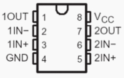
Use only one 1uf capacitor,
found on either board, for isolating both circuits from each other, input & output.
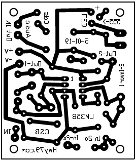
This 2.5"
x 2.1" add-on board below will give you a pitch preview signal only heard
when volume is off and will make tuning the volume response much easier by using either pulse
direction. Only works with my PWM board.