| <=
home .
|
Visit |
|
|
This
approach is an excellent introduction to the Phoenix Electrodeum. Most people can
solder the three EWS connections. - To Recapture the lost Classic Sound is priceless - |
||
This website will be active until March 31, 2021
| <=
home .
|
Visit |
|
|
This
approach is an excellent introduction to the Phoenix Electrodeum. Most people can
solder the three EWS connections. - To Recapture the lost Classic Sound is priceless - |
||
|
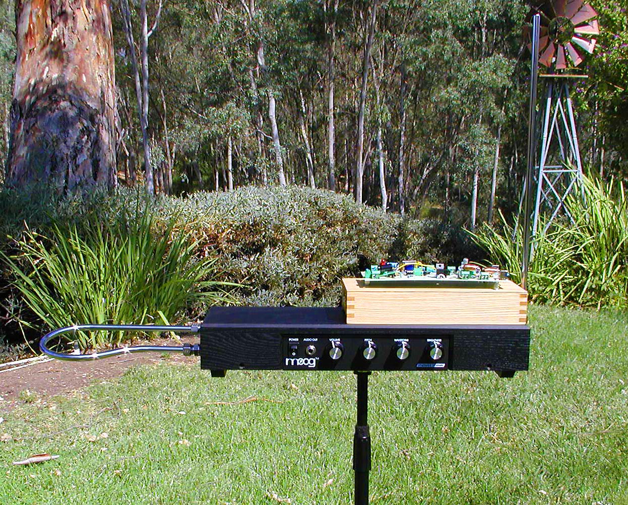
Always use Ctrl-F5 to update this page EtherWave Standard Pitch Mod - The Box -
Parts List Phoenix EWS The
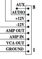
Complete EWS Build List - I still need to take a picture of the EWS three wire TRS connection -
- This idea is New as of 8.26.20, needs study -
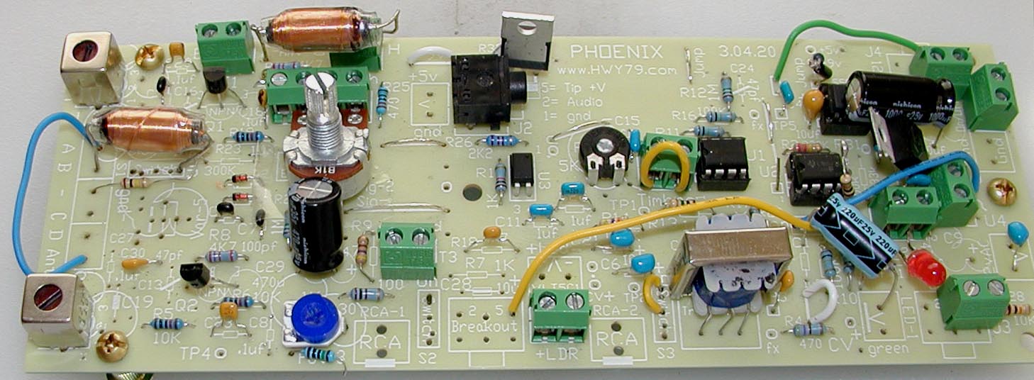
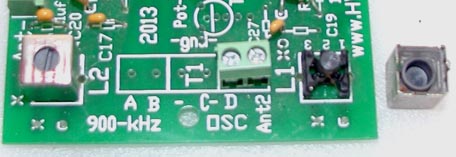
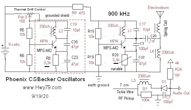
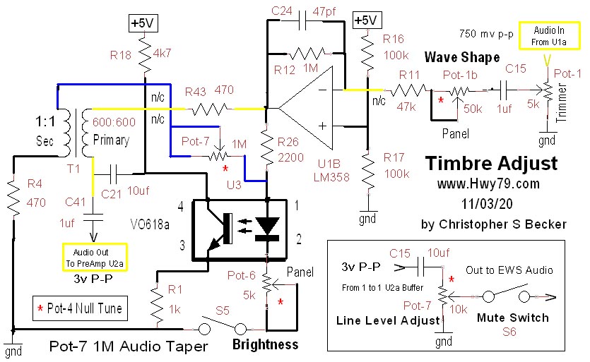
This is the actual Pitch Board as of 9/19/20 - Breaks out of Null below 30 Hz Smooth
Click on image to enlarge Note:
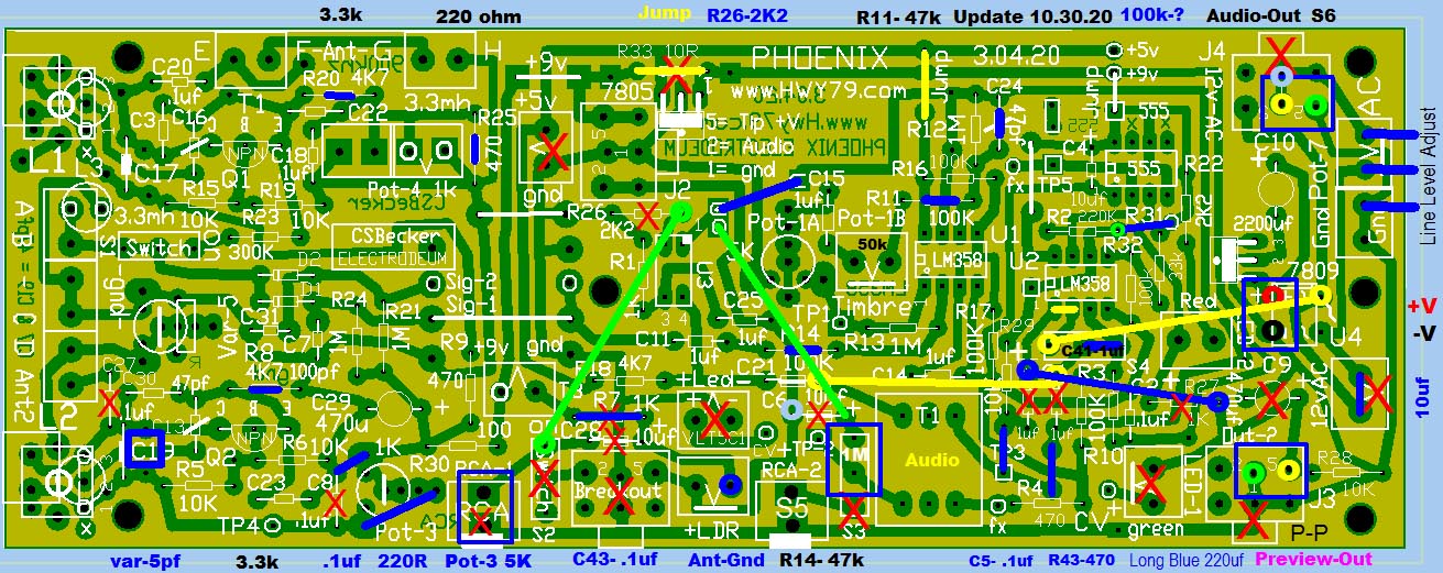
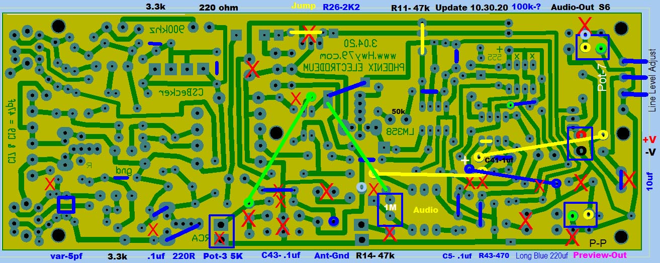
On the 3.04.20
board the IF
Transformer, the side with two pins, one pin should be cut off & not
soldered * I have a working EWS to try this on. Ordered the Box #2, now Box #1 seems prettier *
U2a is used as a 1:1 signal buffer for the Pitch Preview & Audio Out unmod-pitch - Press Ctrl-F5 to update image to 10.30.20 - .
- Click on image for clear enlargement -
|
|||||||||||||||||
.