|
Complete Phoenix Pitch/Volume theremin
just two mouse clicks - Mouser
Parts - about $80 June
2018
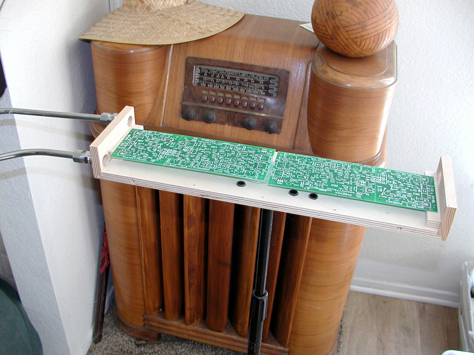
| Stuffing
the Boards - Component Setup
View
this Graphic to see the parts that should be mounted for Step
#1 including eight
jumper wires, the "Do Not Install"
parts
are left off.
2N3904 Transistors are on the Mouser list for the
Phoenix are backup,
three for each board. Use MSA-A42
transistors if available for the oscillators as a first choice, mainly they have a > 300 volt breakdown voltage.
I think this
improves thermal drift resistance which is an effect at the PN
junctions and they also enhance the audio wave shape a bit.
|
Read how to get the free
PCB board
Two boards are needed for the complete project.
Note:
The commercial pcb needs a center dimple
drilled at each TRS jack to accommodate a metal tab and level the jack (View
jack in middle of this page)
Do
Not Install these parts initially - Pot-5, V1, VTL5C1, C9,
LED-1, Q4, S1
& S2, U3
and all parts crossed with symbol "/"
R1, R18, R23, R25, R26, R29, R30, Rx, C6, C12, C21, C25, C26, C28. The Pitch
& Volume boards use a
different combination.
Step #2 The
Rest of the Parts
The ground plate is used under the Pitch Board
only after the board is aligned in the enclosure and the stand-offs are glued into place, it is not used with the
volume control board setup. It may not be necessary at all.
Connect 12 volts dc power to T6
or plug into the Jack
with a positive tip. This connection is diode protected
against reverse polarity.
The audio signal for
testing is at
the Out-2B jack. Use a stereo cable to your computer sound card input.
If
needed revisit View the 3 x 3
Stuffed This test works the same except output the audio through an
amplifier or sound card.
LED-2 (red) works as a
tuning indicator, it will be Off at the Null
and
On
if it detects the heterodyne audio signal even in the range is above human
hearing. (ultra-sonic)
If L1 & L2 are "way out" of tune LED-2 will also be off.
Connect the two boards
together, if you stuffed two, with a 3.5
mm TRS stereo cable plugged into the J2 Jack on both boards.
Only one board needs
12 volts
power connected directly to it. This power is passed through the
J2 cable to the other board. Audio
will only pass
to the Volume Control board after the
Harmonic Enhancement
components and white wires are installed on the Pitch board.
* In the next Step #3 and Step #4 the
Volume Board will need to be tuned 100 kHz lower than the Pitch Board
which is about 800 kHz. An analog AM Radio will come in handy here for
verification of frequencies.
Add this mod if desired
only after
everything is working perfect.
A very faint birdie from
LED-1 can occur, adding
R32 on the modification
webpage eliminates this plus really spreads the quiet side of the volume
response.
The retuning of L1 is always
necessary with any 3 x 3 section circuit or antenna change.
Connect the Phoenix to earth ground and
the Lev Antenna. Once the L1 & L2
adjustments are finalized , only Pot-4 is
used for tuning. The Lev Antenna has two mysterious features, first
it give a perfectly linear pitch field and second where the wire
connection is made it will compensate for thermal drift caused by the environment.
The Phoenix is "thermal drift resistant" as
a bird she was born from fire and rose
from the ashes.
Latest
Board Modifications Found Here
Step #3
Pitch Board Only
Install:
Pot-5
-100k,
C9 = .1uf
Remove
the jumper wire at T1
C-D from both boards and install Pot-5
= 5k on the pitch board only.
Extra power supply filtering is recommend
on the Pitch board at the +9v Jumper wire. (See
Mods) R31 & C29
LED-2
can use connecting wire so it can occupy the
wood box hole drilled for LED-1
which is not use on the Pitch Board. LED-2
can be any type or color, LED-1
is critical
and must be on the Volume Board
only.
Install the
Audio Enhancement parts for
the best sound.
This audio is passed through the J2 cable to the Volume Control.
C6-1uf C21-1uf
C25-1uf
R1-1K R18-10K R26-2.2K R29-2.2K
V1-Transformer with P facing towards Pot-1, this is the same area the
Vactrol V1 mounts on the Volume Control Board.
U3- VO618A Opto, dimple to #1
Note:
Mount C25 & R29 with longer leads above the board so
they can be clipped and resoldered for testing for the best effect.
Install the two (white) Jumper wires for
Audio Enhancement activation (See
Mods)
The main reason not to
have a ground under the L2 side is that it could interfere with inside pitch
linearity of the
Lev Antenna.
Out-2B
is used for a pitch
preview on the
Pitch board. Custom wire in an internal headphone amplifier in the box or
use one side
of a stereo Eq-Pre Amp to prevent any loading distortion on the Phoenix audio signal.
For
Perfect Pitch Field Linearity
use the Lev
Antenna concept and for Volume Control anything metal works. You want
to avoid direct contact
with the volume side antenna so insulate it with a plastic sleeve or run
an insulated wire inside the loop.
If the Lev Antenna is
not desired, a 3.3 mh coil is on the parts list to test in series
with a regular 18" rod antenna.
After the enclosure has its
holes drill and the PBC standoffs are glued into place, the Pitch board
will need a
2" x 2" ground plate with a 2"
wire soldered to it
under the L1 half of the 3 x 3 section of the board.
Have the ground plate copper side away
from the solder
connections under the L1 half of the osc
board. Hold this in place with double adhesive foam tape. (See
Mods)
The ground plate wire is
connected at the terminal T1.
The ground at D
is variable using Pot-5
for a more adjustable effect or just use C which is a fixed ground
connection.
Step #4 Volume Board Only
a name="anchor">
Install:
Vactrol
VTL5C1, green LED-1, C9- 1000uf,
C6= 10uf on left
side of Vactrol
Input-1 & Output-1
TRS Jacks, & R34-10K
(See
Mods)
C17 & C19
only on the volume board
3 x 3 should be 100pf
to move the frequency away from the Pitch Board frequency.
The Volume Control "will
not" work without
the green LED-1
installed.
See Modification R32-2.2k
(See
Mods) This is for expanded
shading on the quiet side.
R33-4K7 was added on the volume
board only. This quiets a hiss sometimes heard at low volume. (See
Mods)
Pot-5 100k
trimmer is installed on both the Volume and Pitch boards.
A
100K
(68k?) resistor is installed from
B to Ant2
at the ABCD terminal to get the proper wave shape for volume.
Do not do this at first, try the ABD wiring method
like on the pitch board, tune Pot-5 100K for wave shape. see
here
Make the volume loop antenna connection
at the Ant-
terminal not
Ant2 or which works best.
Note: Some sound cards display this wave shape inverted
when it is not! If you really have
a pointy up wave form with your volume response will be more on/off,
with little or no shading.
See the Volume
Wave Shape webpage. This covers how to get the proper wave shape.
Volume Control needs a spikier
waveform in the negative going direction. This can be scope viewed on the
right side of C1 as a upward spike 0 to 500
hz 1 volt p-p. You could record the signal into Audacity
out Out-2B and spread
it out to
view.
NPN Transistor Q3 flips the upward
spike downward for proper operation of the 555 trigger pin-2.
Almost any thing works for the volume side
antenna. You could fashion a Loop
or use a straight rod.
I have considered using a paint roller metal rod. View
Roller Rod .jpg
The best
volume antenna would be a rubber
coated wire, feed this through a
metal or plastic loop or other form.
With the Phoenix board used
for
volume
control, the board indicator red
LED-2 will “turn off” at the Null
Point which is the loudest volume, and green LED-1
will be at it's brightest.
If green LED-1
is Off no
sound can pass to the main amplifier. The Mute
switch
turns off green LED-1.
The green LED-1
might be mounted so it is visible to the Thereminist.
Use the Phoenix volume control
with any
pitch only theremin
or change that
righty to a lefty. You can position
the Phoenix volume control anywhere around you for comfort, especially for left handed playing. Using
the Vactrol is a true resistive
volume control and it adds
no
distortion
to the original sound. (Keep
signal level below 1v p-p)
Note: The Vactrol overdriven will flatten the audio signal peak; which adds distortion in the sound. This can be easily viewed in Audacity recorded from the Volume Control Output-1 TRS stereo jack.
Turn Pot-1 on the Pitch board down a bit, CCW, this solves the flattening.
Mount the PCB's in their enclosure and
connect the antennas. Retuning of L1 & L2 will now be necessary. You
want the pitch board to be around 900 kHz and the volume board around 750 kHz.
Use your imagination to set the Phoenix up,
mount the enclosure if using two on their own tripod or base.
Earth Ground is so important
to the proper theremin sound that I
advise using a power receptacle strip that has a
green
LED ground indicator. The
LED should light steadily. Everything
should plug into this one power strip.
Connecting the Phoenix
Output-1 to a power
amplifier which uses a three prong power plug is one method to get ground.
Visit the
Black Box ground
for the Phoenix.
Output-1
on the Volume Control board can be reconnected to use the
Out-2B
Jack so no 1/2" holes need to be drilled in the side of the box, just
the bottom.
My method to avoid
ground loop hum
is shown on the graphic of the cable layout on my Phoenix
Cables webpage. Using the ground loop isolator and the shortest cables are good
ideas.
theremin@oldtemecula.com
Design by Christopher
|